In a first post, I went through the content of the kit. Taking pictures of all the parts was nice, but assembling the keyboard is even more fun! Again, I took quite a few pictures, I hope it’ll be useful somehow.
This is the second article of a 3 articles series:
- XD87 Kit content
- XD87 assembly (this article)
- XD87 firmware/layout customization
- XD87 firmware extra: QMK instead of TMG
Preparing
The first is to make sure you have everything you need to assemble the keyboard. Let’s make a quick list of the keyboard parts needed. Make sure you have all you need before beginning, it’s always annoying to start and realize you have something missing and having to wait for it to be delivered.
- PCB
- steel plate
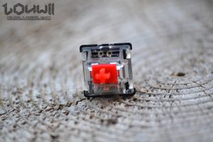
- switches
- stabilizers
- USB module or female USB connector
- RGB SMD LEDs (optional)
- 2 pins LEDs (optional) / SIP sockets (optional)
- case (optional)
And now, the tools!
- soldering iron with a pointed tip
- solder
- small screwdriver (for the case)
- DSLR camera (hm, well, that depends on if you want to share your work or not)
The soldering iron I have is nothing fancy. I bought it for $20, it has a small pointed tip which makes it easy to do through-hole soldering, but is also thin enough to solder those damn SMD LEDs.
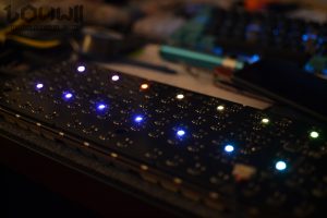
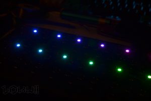
SMD RGB LEDs for underglow
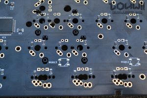
Talking about those, they are optional. The case included in the kit doesn’t have anything to show the underglow lighting. I decided to solder them anyway, because I like the challenge (and also because RGB underglow is kind of sexy). They are really small and the soldering pads are tiny tiny.
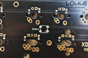
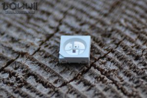
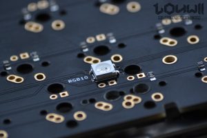
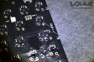
First, make sure to align the LED properly. One of the corners has a cut, and needs to be aligned with the “triangle” shape on the LED schematic on the PCB. The technique I used was to add a bit of solder on 1 of the 4 pads but not too much (there’s already a bit of solder on them, but I wasn’t sure if it was enough…). Then place the SMD LED properly on top of the 4 pads. It’ll be slightly off balance because of the solder you added previously. Push it down slightly (make sure it stays aligned with the pads on the PCB) while melting the solder on the pad. The LED should slightly go down into the melted solder. Remove the soldering iron, wait 1 or 2 seconds for the solder to solidify and there you go. The LED should be properly in place and won’t move anymore.
Soldering the other pads is not easy, but doable. Just add a bit of solder between the LED pad and the PCB pad, where they join, on the side of the LED. I know it’s not the proper way of doing it, but it works fine, as long as you don’t overheat the LED, they are quite sensible (I burned one because I left my soldering iron tip on one of the pads for too long). Try to do it in 1 or 2 seconds.
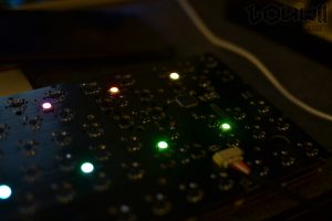
If you want to test if the LEDs are working or not, make sure you solder them in order (RGB 1, RGB 2…). They won’t light up otherwise. My keyboard always have the LEDs turned on but default when I plug it in (it was like this when it arrived). Every time I soldered a LED, I plugged in the PCB and checked if it was working properly or not. As I said, I burned one with my soldering iron, and it was a pain to remove. Another one burned down because I didn’t pay attention to its orientation when soldering it. I had to buy some new ones (WS2812 or SK6812).
This is the result, without the case on, obviously.
Preparing switches for SIP sockets
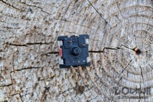
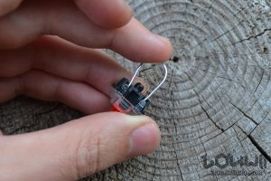
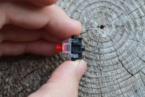
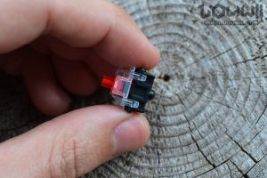
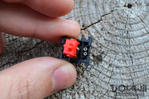
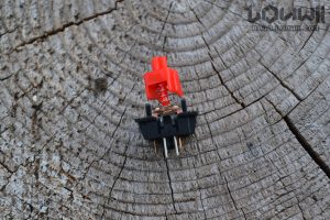
Now that I got that out of the way, on to the next boring step. The keyboard has regular backlighting LEDs that you have to solder. In order to easily change the color of the LEDs (meaning, changing the LEDs), I bought some SIP sockets. SIP sockets are soldered in lieu of the LEDs, and you just have to plug the LED into the socket and you’re done. The fun part is that the sockets need to be installed inside the switch. And to do that, you have to disassemble the switch. So yeah, I did that, 87 times. All of this is optional. If you don’t need backlighting, you can ignore this altogether. If you don’t mind not being able to change the color of the LEDs easily, you can solder them directly, no need to disassemble the switches.
Stabilizers
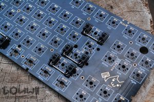
Last preparation step: adding the stabilizers. Please don’t repeat the same error I did, add the stabs before soldering switches. Otherwise you’re gonna have to de-solder everything, and that’s even less fun than installing sockets into switches.
The stabs need to be installed in a certain way. First, the stabilizer stem need to be inserted into the stabilizer base (make sure to respect the direction). The stab has 2 pins, a big one and a smaller one. The big one goes first, into the bigger hole on the PCB, smaller one goes after. You’ll have to push a bit and make sure the stab correctly clips into the PCB. It needs to sit flush.
Then you need to install the bars. Insert the bar into the stem, and push the bar down to clip it into the stab base. Mine required a good amount of force to go in.
Soldering the switches
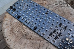
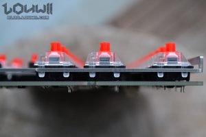
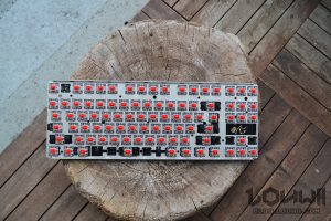
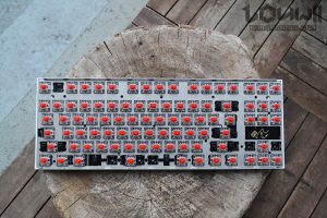
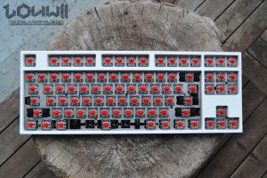
Switches ready, PCB ready, steel plate ready, onto the main soldering part. Fortunately, this is fairly easy. Place the steel plate on the PCB, its bent edges facing upwards. Then place the switches. Switches need to be flush with the PCB, and they clip into the steel plate. I suggest to put at least 4 switches first, one on each corner, and then solder them. That way, the steel plate won’t move and it’ll be easier to insert the other switches.
Soldering the switches is easy, it’s just standard through-hole soldering. The pads and switches connectors are quite big, I think it’s a good way to train yourself to use a soldering iron. Soldering LEDs or SIP sockets is a bit more difficult as the connectors and solder pads are smaller. Take your time, make sure to have good lighting, use a magnifying glass if needed. You’ll get there eventually.
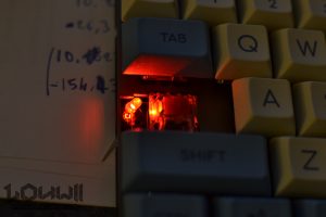
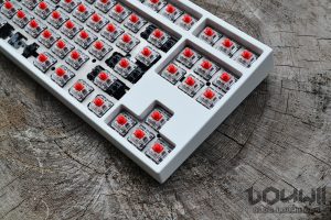
As you can see on the second picture, there’s a little slot on the left side, on the left of a switch. That slot is for a capslock LED. It’s actually pretty neat, it lights up when capslock is on, as you might expect. I’ve used a 3mm LED but I think there’s enough space for a 5mm one.
Testing
When you’re finally done, or even from time to time after soldering 5 or 10 switches, you can test the keyboard using software, or even websites. I recommend Aqua’S KeyTest. It’s a software running on Windows only. Using a website is fine but you might trigger unwanted actions when pressing keys, while the software “catches” everything.
Final assembly
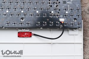
Well, there’s not much left. We make sure to connect the USB module first, and then install the entire PCB/plate/switches contraption into the bottom part of the case.
Inserting the top part of the case can be a bit tricky as the fitment is tight. I had to put a bit of force into pushing the top part until it clips properly on the bottom part. Once it’s done though, the keyboard is super sturdy; nothing moves, nothing bends.
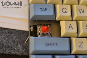
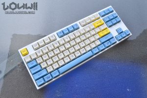
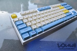
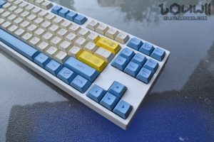
Now, the finishing touch: keycaps! Not a lot to say about it. I like to put o-rings on my keycaps to attenuate the sound and feel when the key are bottoming out. But that’s optional. They keycap set I chose is a copy of Godspeed keycap set, the keycaps are DSA profile. I really like them, they have their own style, they’re not boring, DSA profile is really nice and they fit well with the creamy white case.
That’s it! Honestly, I’d like to build more of those but there’s no point of having 3 times the same keyboard, right? 😅 It was a fun built and the keyboard is just perfect for me.

Could you take a photo of underglow lightning? Thinking if I need to do it or not…
PS Captcha in French is kinda hard.
XD84 supported by qmk
https://github.com/qmk/qmk_firmware/tree/master/keyboards/xd84
That’s not the same keyboard though. This is the XD87, not XD84 as you linked. The XD87 is now supported by QMK too though. I wrote a blog post about it recently. https://blog.louwii.com/2019/10/xd87-tkl-keyboard-kit-qmk-firmware/
Hello,
I’ve ordered that same PCB and I was wondering if the switches that I got:
https://www.aliexpress.com/item/32980039972.html?spm=a2g0s.9042311.0.0.39e54c4d75xyGK
Would they work with the PCB and individual leds for each switch? the PCB supports that, right? I see two little holes on the PCB.
(sorry for the ultra late answer)
Yup, you’ll be able to put individual leds for each switch. I’m using SIP sockets so I can add/remove LEDs as I want, but you can solder the LEDs directly to the PCB too.
I’ve seen this on kprebuplic and they have kits with added stabilizers. One thing I’ve been struggling about are the keycaps. I’m not sure if they’d fit. Will these work?
Keycaps:https://aliexpress.ru/item/33016899092.html?mb=j3oGRk0OMKOW5Dy&srcSns=More%E2%80%A6&tid=white_backgroup_101&tt=sns_More&image=H712dd90829ee453b8dc57cf81340b0b5v.jpg&aff_request_id=54f1ff665dda478b9b318efbcaa7870e-1593978381467-09471-_d8QK4Of&spreadType=socialShare&aff_platform=default&sk=_d8QK4Of&aff_trace_key=54f1ff665dda478b9b318efbcaa7870e-1593978381467-09471-_d8QK4Of&businessType=ProductDetail&templateId=white_backgroup_101&title=US+%2412.99+%7C+104%2F87+Key+PBT+Double+Color+Backlight+Mechanical+Keyboard+Keycap+Large+F+Universal+Column+For+Ikbc+Cherry+MX+Mechanical+Keyboard&platform=AE&terminal_id=45eacaa28b34445c9ee6af07393a43b1
This PCB is compatible with MX switches style (Cherry MX, Gateron, all the ones with a “+” stem on the switch). So you can buy any keycaps that are compatible with MX switches. The ones on Aliexpress are compatible with MX switches so you’re good. Also, make sure you get switches with your keyboard 🙂
Thanks so much for writing this up! I documented my notes on this build today, but mostly just followed what you have put together here.
https://digitalcardboard.com/blog/2020/07/30/kprepublic-xd87-tkl-kit-build-notes/
No problem! Thanks for linking to my blog post on your article 🙂
Hey, sorry to resurrect this old post. I made an XD-87 a while ago for myself, and the build went smoothly.
I’m building another one, as a gift, and I was wondering how the underglow looked with a white plastic case. RGB is not a priority on my own build, but for this New build I’m considering it. Does the RGB bleed through the plastic at all? Based off intuition it shouldn’t given my white case is opaque plastic… but it also isn’t very thick, so I could see the possibility of bleedthrough.
Unfortunately, the RGB underglow is totally invisible with the white plastic case. You do see it a bit when looking at the bottom of the case, which nobody ever do.
Gotcha. Maybe my next project is to CAD an acrylic case for my XD87… would be a fun project 😛
Thanks for the swift response!
If you ever end up creating an acrylic case, please please please let me know!! I would really like to try that! I’ve got a shop near my place that can cut acrylic.
Building an acrylic case for this keyboard will be quite difficult, considering the unique way the plate mounts into the board. Regardless, I’ll let you know if I ever do design one, though it might take some trial and error and that can get expensive (in other words, might take a while).
PM me on reddit and I’ll try to update you (/u/LargeHadron_Colander)
https://imgur.com/a/1Q1YI1w
Nice! Although this has its own plate, it’s not using the aluminium one from the kit.
Hello Louwii, thanks for the blog.
Before soldering like you, i tested each key and 2 of them dont work, the right Alt and the right Win (next to each other). Did you have the same issue ?
I tried also to flash the PCB with default layout (with QMK or TMG) but this two keys dont work anyway.
Bastien
I don’t remember having any problem with those two keys. Are you sure they’re set as alt and win in the mapping? If so, then you might have a defective PCB, it happens sometimes. It might be fixable though, but that’s not something I can help with. I would start asking /r/AskElectronics.
Im sure
I also tried to short cut the circuit for both of them. it works for the win but for the alt, the short cut call the alt and the ctrl . I think i have a défault one. Maybe i will change for the xd87 HS one because it seems more reliable…
Do you have a meter to test the traces for continuity?
Keyboard PCBs are pretty easy to fix with trace wire and a solder iron.
Good program to test keyboards with.
https://www.majorgeeks.com/files/details/switch_hitter.html
Yes i have one. I think i found the traces continuity but i will try with the meter to be sure. I also will try switch hitter .
Thanks for helping
[quote]
Please don’t repeat the same error I did, add the stabs before soldering switches. Otherwise you’re gonna have to de-solder everything, and that’s even less fun than installing sockets into switches.
[/quote]
Thanks for the great write-up. I wish I read it before soldering and then looking up how to assemble the stabilizers. :”(