One of the best feature of the XD87 PCB is that its firmware is fully customizable. Although this might sound complex and probably way too much, customizing the firmware allows you to create your own layout for the keyboard. Let’s dive in. Don’t know what I’m talking about? See this article first.
This is the last article of a 3 articles series:
- XD87 Kit content
- XD87 assembly
- XD87 firmware/layout customization (this article)
- XD87 firmware extra: QMK instead of TMG
Note: I’m just providing indications on how to customize and flash the keyboard. That’s how I did it and it worked for me. However, I won’t be responsible for any damage you do to your keyboard. That’s how DIY works, you do whatever you want, the way you want, and you’re accountable for everything you do.
Customizing? Firmware? What?
I doubt that if you’re here, you don’t know about keyboard customization, but I’m gonna explain it a bit.
The firmware is the software that runs in your keyboard. The software interprets what key you press and reacts accordingly. The reaction can be to send the key command to the computer (I pressed “e”, the computer receives that press and insert a “e” in my text editor), but that can also be internal actions, like turning the backlighting on or off (in that case, nothing is sent to the computer).
The XD87 PCB firmware is open-source, meaning you have access to the actual source code. Here’s the pull request with the code if you’re interested. The firmware is using TMK (a keyboard library for keyboard firmwares). It’s not as popular as QMK but it’s functional enough. It’s possible to convert the firmware to use QMK, if you feel like it.
Edit: 1 month after writing this blog post, fougner posted a QMK firmware for the XD87. This blog post is only for TMK. I wrote up a guide for using QMK as well: read the blog post.
As the code is open source, you can do whatever you want with it, even modifying it, generating a new firmware and installing it on your keyboard. Be careful though… Because you can also easily break it.
What we’re going to do here is actually modifying the firmware slightly so that some keys do whatever we want them to do. It’s super easy as there are tools to facilitate the task, no coding skills required!
KPRepublic provides some instructions on their Google Drive to help you customize the layout and flash the keyboard. I’m going to explain the process again here, with a bit more details.
Customizing the layout and features of your keyboard is a 2 steps process. The first one is to define the main layout of your keyboard, basically which key does what. The second step is to generate a firmware with your layout and flashing it to the keyboard.
Keyboard layout
Customizing the layout is very easy as it’s done via the Keyboard Layout Editor (or KLE) tool.
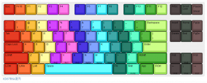
KPRepublic provides a default layout for the XD87 there so you can get an idea of how it’s done (I’m not sure what the colours are for). Also, that layout has set roles to the 3 unusual keys that I can’t use due to the case I have (see XD87 TKL keyboard kit – Kit content).
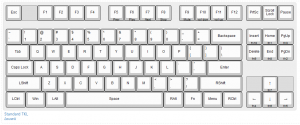
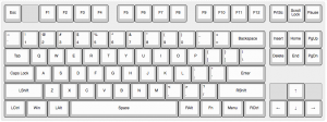
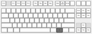
You can either start from scratch and replicate the layout, start from the “official” layout from above, or use mine that you can find there. I tried to keep it simple and functional, nothing crazy. It only uses 2 layers.
As you can see, each key has a general label (layer 0) and some has a second label (layer 1). That label is important as it defines what the key will do. You can’t enter just anything you want in there, the firmware needs to “understand” what the key is for. If you put an unrecognized label on a key, it won’t do anything. Fortunately, TKG (the firmware generator tool) has a list of all the keys and their corresponding label, you can find that list here.
Other important things to keep in mind when creating your layout:
- you have to put all switches in the layout, including the 3 unusual ones (between the Esc and F1 keys, and one on each side of the top arrow key).
- you have to use top legend or centre legend to indicate what the key is supposed to be. That’s the layer 0 of your layout.
- you use front legend to indicate the “second” role of the key when pressing the fn key. That’s the layer 1 of your layout.
- you can set up to 32 fn actions (fn0, fn1, fn2… fn32). fn actions are use for specific actions available in the firmware itself. In the next step, when using TMG Keymap Generator flashing tool, we will link an fn action to what it’s supposed to trigger (backlighting, underglow, layer features…)
About layers
The XD87 PCB can handle up to 8 layers, 0 to 7. The layer 0 is the default one, the one that’s active by default.
KLE allows only to set layer 0 and 1 in one combined layout. If you want to create more layers, you’ll have to create a separate layout for each of them and use only the top or center legend for each key. You’ll be able to set which is which later on when generating the firmware.
If you’re not sure what a layer is, here’s a quick explanation. A layer defines an action for each key. As you might have seen on laptop keyboards, some keys can have a second action, like play/pause, or increase/decrease volume. Those secondary actions are defined on a second layout. The usual behavior is to set the FN key to momentarily activate the layer 1. That basically means when you maintain the FN key down, the layer 1 is active. When you release it, the keyboard is back to layer 0. That’s on layer 1 that the key will have a second role, like play/pause. In my layout, I’ve set some F keys on layer 1 for media and sound control.
The XD87 is pushing this quite far as you can have up to 8 layers. But how can you access the other layers? Having 7 FN keys on a keyboard doesn’t make sense. Well, you can also customize the way you want to access layers too. For instance, instead of having to maintained the FN key down, you can set it so you just have to press and release it to activate the layer 1, do whatever you want on layer 1, then press-release FN again to go back to the layer 0. Everything is controlled via fn actions. We’ll get back on that later.
Generating the firmware
TMK Keymap Generator (or TKG) is a really cool tool that will generate a firmware for you, using layout data from KLE. The tool allows you to choose your PCB, input your layout layer(s), set your fn actions and generate a firmware for your PCB.
Important note: the normal TKG site is accessible via https://tkg.io but it doesn’t have the XD87 PCB in the list. You need to go to https://xd.tkg.io to be able to generate a firmware for the XD87.
Important note 2: you’ll need to enable the advanced mode. On the website, click on Tools -> Advanced Mode.
I’m going to divide each section like the site does.
General
Choose the right PCB: XD87 (do I really need to write that?).
Layer
As I explained before, there are 2 ways of entering your custom layers, depending on how you created them on KLE.
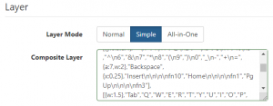
- if you’ve created 2 layers combined, choose the Simple layer mode. On KLE, go to the Raw data tab, and copy the entire text. Back on TKG, paste the text in the Composite layer text box.
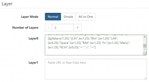
- if you’ve created more than 2 layers, choose the Normal layer mode. The idea is the same, copy the raw data of the layer on KLE, paste it in the designated layer text field on KLE. Use + and – buttons to add/remove layers.
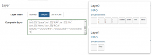
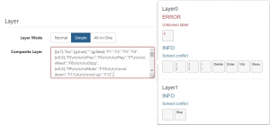
TKG will verify that your layer doesn’t have problems. After pasting the layer data, click anywhere else on the page (even on the white background) to trigger the validation . If everything’s good, the box will have a green border. If not, it’ll be red. Clicking back into the text box will show a popup with either some information about the layer, or the problems detected in your layer.
Fn – custom functions
Custom functions are functions/features defined in the keyboard firmware. As I explained earlier, you can define up to 32 function keys (fn0, fn1… fn31) in your layer. It’s now time to associate your function key to a firmware custom function.
As you will see, there are some default ones. You don’t need to keep them, of course. The first one, Fn0 Layer action > Momentary, Layer 1 is the common behaviour for an FN key (as I explained before). You maintain the fn0 key pressed and it activate the layer 1, you release it and it’s back to layer 0.
I won’t go in details about each function though, you’ll have to do a little research by yourself 😉 You can trigger layers, trigger a key, trigger a combination of keys… Backlight actions are for keys backlighting. For underglow, you need to go to Other -> Built-in function -> RGB LED and then you’ll have access to different actions for underglow lighting.
LED
I haven’t dug through that part a lot, I’m just using what’s recommended by KPRepublic.
- Caps Lock: Active Low, binding Indicator, indicator Caps Lock, no reverse, no backlight
- Backlight: Active Low, binding None, no reverse, ✔︎ backlight
- RGB Underglow: RGB LED, number of led 16
Flashing
I’ll cover only “online flashing”: flashing the keyboard directly from the TKG website. There’s also an offline flashing method that uses a command line tool. a bit harder to use.
First, you’ll need to install a Chrome (or Chromium) plugin. Download it from the Google Drive (tkg-chrome-app.crx) and install it in Chrome. In Chrome/Chromium, go to chrome://extensions/, and enable the developer mode. Drag and drop tkg-chrome-app.crx into the Extensions window. Chrome will ask you if you want to install the extension, choose yes, of course.
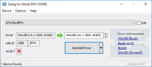
Then, you’ll need specific Windows drivers, otherwise your keyboard won’t be detected when switched into flash mode. For this, the easiest way is to download Zadig. Start the program but don’t do anything yet.
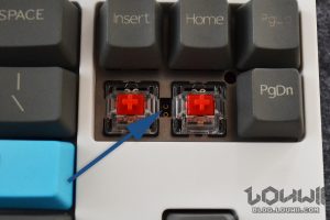
Plugin your keyboard and switch it to flash mode. For this, you have to make a short between the 2 top pins of the ISP1 expansion port. Fortunately, that’s pretty easy to do even when the keyboard is assembled. They are accessible between the Delete and End keys. Use a pair of tweezers or a piece of wire to make a short between the 2 pins. Windows should play its usual “a peripheral has been disconnected”, “a peripheral has been connected” sounds, meaning the keyboard has been disconnected, the flashmode keyboard has been connected.
When correctly in flash mode, Zadig should detect the keyboard (the dropdown should display ATm32U4DFU). Click Install Driver (note: the screenshot below shows Reinstall Driver because mine is already installed).
Once done, go back to TMK. The Burn .eep file button should be active now. Click it and wait until the operation is complete. The keyboard should then reboot with its new firmware, and the layout(s) you created.




how to flash in linux?
I don’t know. It’s just easier to flash on Windows so I do it on Windows.
TMK has a guide on their Github https://github.com/tmk/tmk_keyboard/wiki#flash-firmware
It might also be possible to flash it online using TKG but I’m not sure as I haven’t tried. You can try though, just skip the parts with Zadig, switch the keyboard to flash mode and see if TKG detects it.
I’ve tested this PCB with QMK firmware uder linux. Several days ago QMK project add support of XD87. Nothing special. Follow QMK documentation.
make xd87:default:dfu
thats all
Is the position of the FN key fixed or it can also be remapped? I’d prefer to have the Win/Super key to the right of RightAlt and the FN key after:
Right Alt – Right Win/super – FN – Right Ctrl
Any key can be anything, you can chose whatever suits your needs. That’s why custom firmwares on keyboards are awesome.